4. Computer controlled cutting
Group work
The laser cutter we were using is an Epilog Laser Fusion 75W CO2. Together with the other students we tested the kerf, speed and power of the laser cutter for a specific material. More information on that and how to operate this laser cutter can be found here.
The group work helped me understand the machines better and achieve good results without extensive trial and error.
Individual assignments
Laser Cutting
Parametric Deign
In this little project I want to get familiar with the parametric design by designing simple figures.
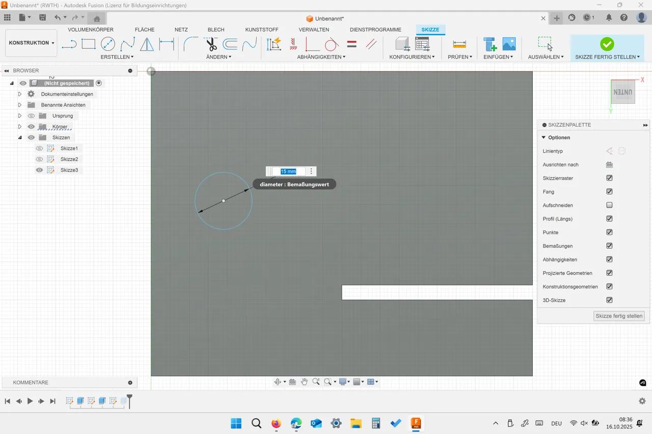
I started by creating a new sketch in Fusion 360. Instead of drawing with fixed dimensions, I used parameters to make the design easily adjustable later. In Fusion 360, parameters are defined under Modify → Change Parameters.
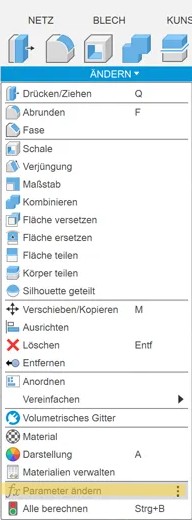
There I created named variables for all key dimensions, for example:
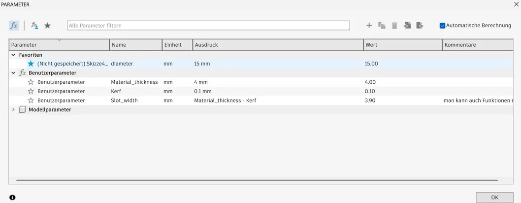 Then while sketching I didn’t type numbers directly. Instead, I entered the parameter names (e.g. Slot_width/2 or Material_thickness*2). This ensures that if one parameter changes, all dependent dimensions update automatically.
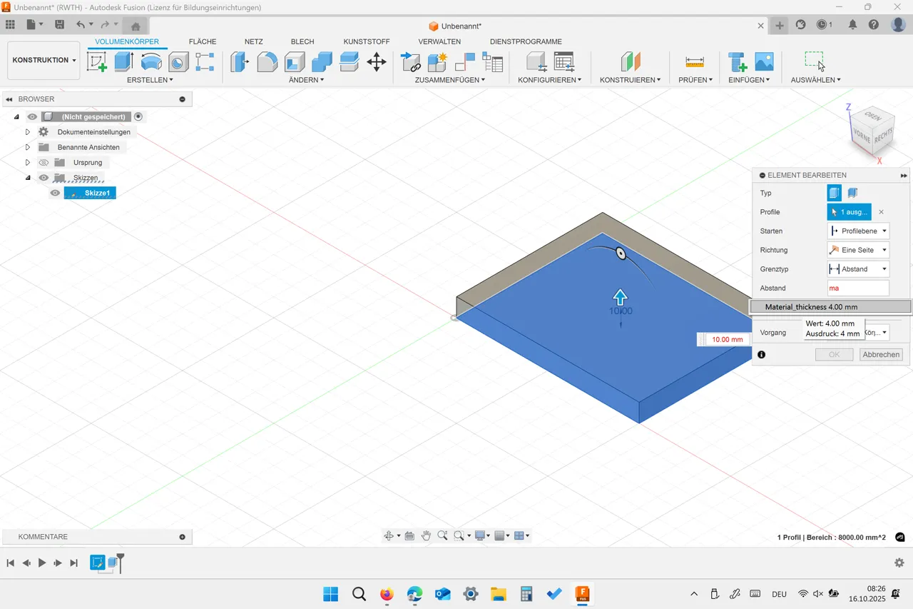
After finishing the sketch, I used the Extrude feature to give the model thickness, also referencing the Material_thickness parameter.
Then while sketching I didn’t type numbers directly. Instead, I entered the parameter names (e.g. Slot_width/2 or Material_thickness*2). This ensures that if one parameter changes, all dependent dimensions update automatically.
After finishing the sketch, I used the Extrude feature to give the model thickness, also referencing the Material_thickness parameter.
 To test the parametric design, I changed the thickness value from 4 mm to 8 mm. The entire model automatically adapted to the new dimensions — without needing to redraw anything.
This demonstrates how a parametric design allows fast iteration and reuse for different material sizes or design versions.
To test the parametric design, I changed the thickness value from 4 mm to 8 mm. The entire model automatically adapted to the new dimensions — without needing to redraw anything.
This demonstrates how a parametric design allows fast iteration and reuse for different material sizes or design versions.
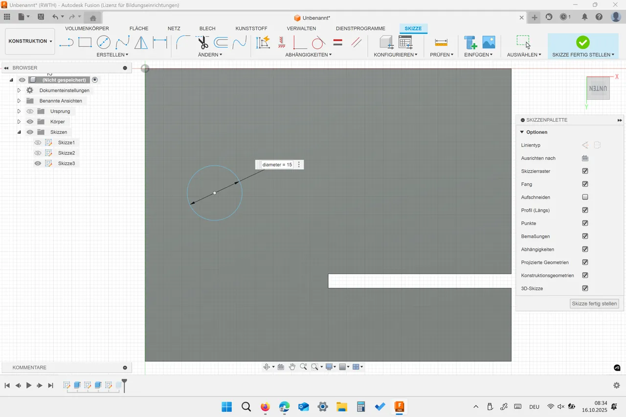
Good to know: if you don’t want to open the “Change Parameters” window to set parameters, you can also just type “parameter_name = value” when dimensioning your sketch. The parameter automatically appears in the Change Parameters table.
FlatFab
I wanted to create a press-fit construction kit. I had previously heard about a program called FlatFab and wanted to try something with it. To get ideas and also a template, I went to printables and found a cute kit-card. So I went to create a dino in FlatFab:
The dino is not simply an uploaded 3D model; I designed it myself, drawing a bit of inspiration from a kit card I found on Printables.
First the FlatFab interface and shortcuts are hard to understand, but after watching the tutorials on modeling it was easy to work with the program.
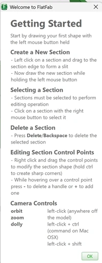
When opening a new FlatFab file, the program schows you the most important control keys:
First of all you have to enable the symmetric creation mode if you don’t want to start with a symmetric body. To do that you have to click on the rectangle in the upper right corner.
I added an image to trace the edges for my main figure:
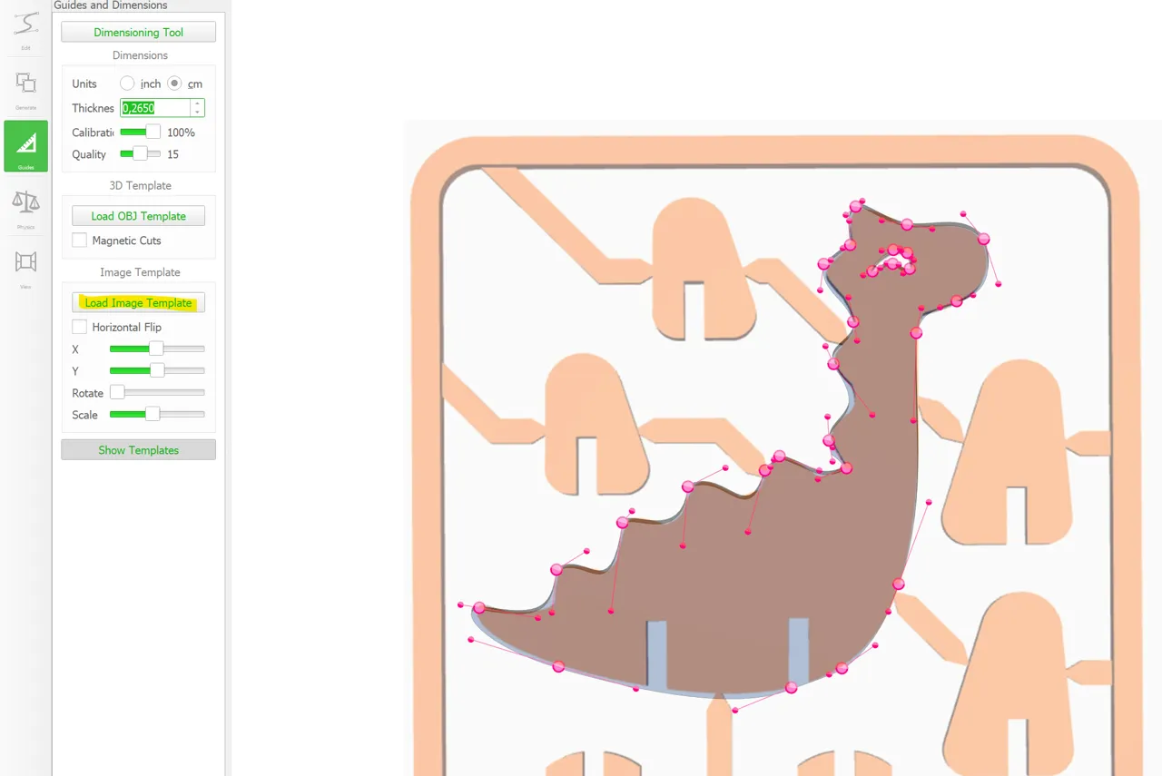 After roughfly sketching the outline, you can still make changes to your design by editing the control points:
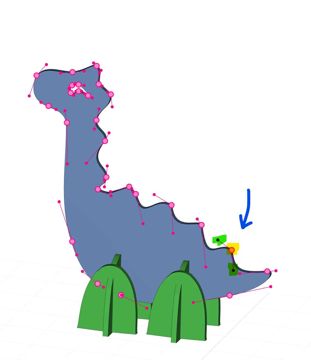
You can also add and remove points if needed (see getting started picture).
To create a connecting piece, you have to draw a straight line on an excisting tile. The software will automatically mark the start of the slot with a red point and the end with a yellow one. You have to start the slot from the middle to the edge of the tile:
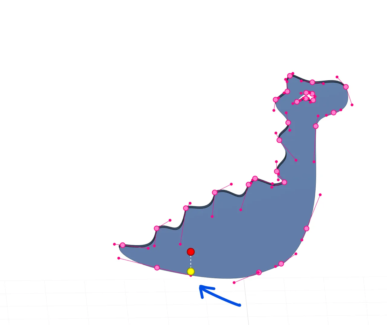
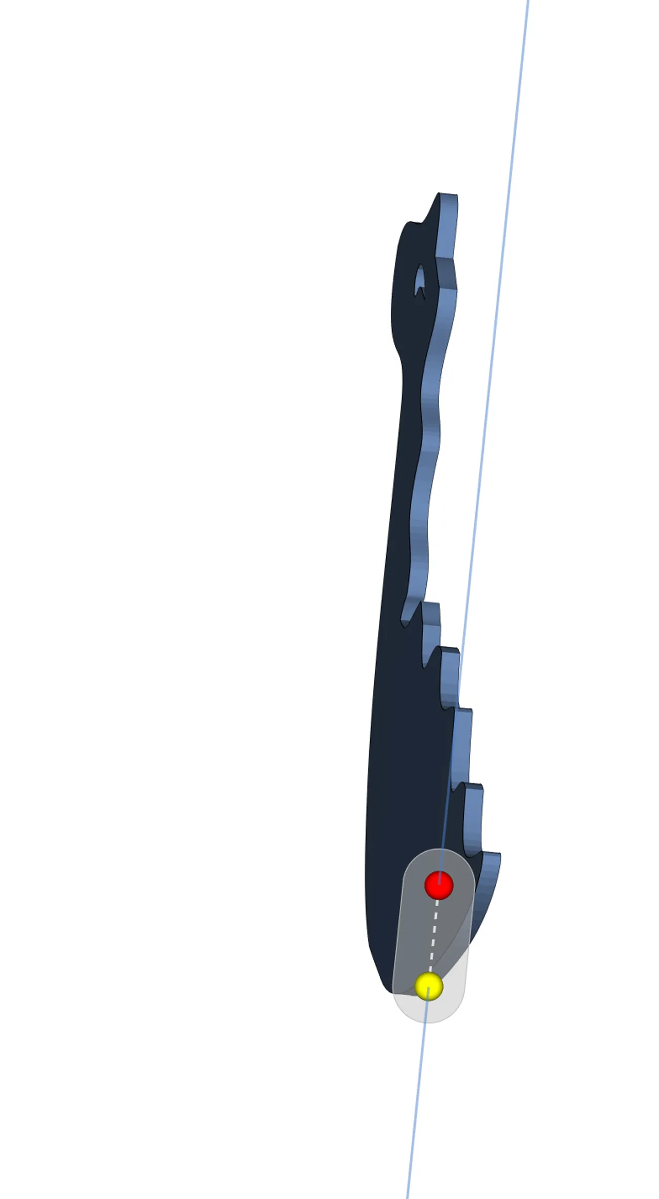
After coming to the end of your slot, the pice will automatically turn and you enter the drawing mode for your new tile. In the grey zone you can move freely without drawing anything but once you leave that area you will start drawing the boarder of the new tile:
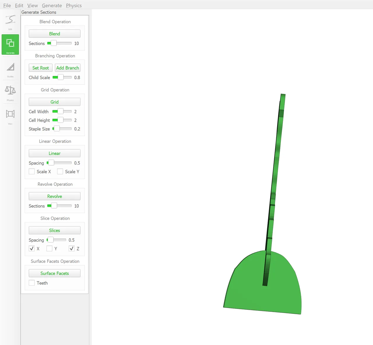
I put on the symmetry here to create a symmetrical piece for the feet:
There is also the possibility to duplicate a tile if you need the tile several times. I did that for the feet of the dino:
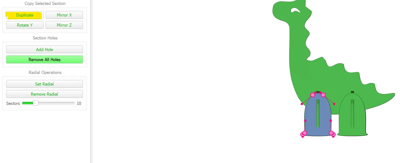
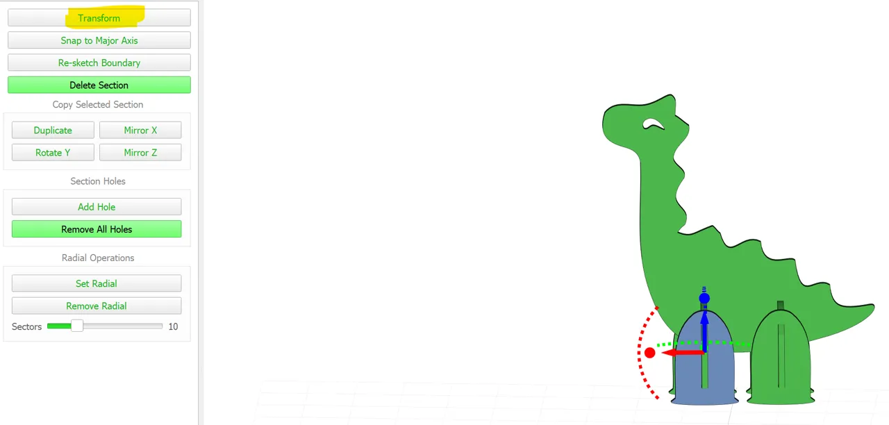
After duplicating, you can go to transform and move the tile to the desired place:
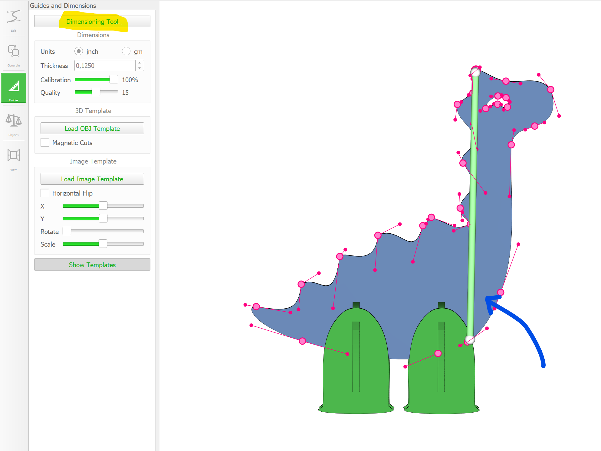
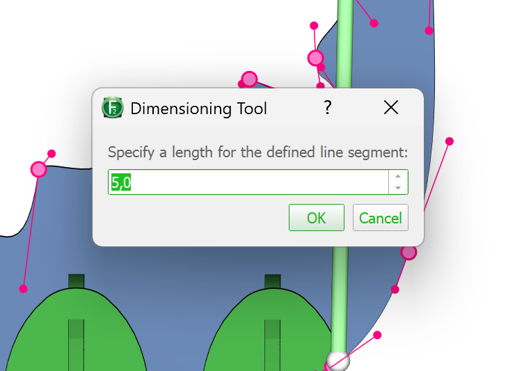
Don’t forget to scale your model:
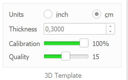
And adjust the material thickness:
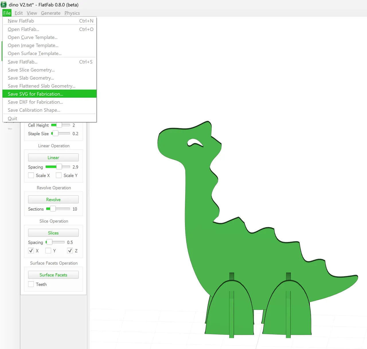
Once you’re satisfied with the look of you model, you save it as an SVG:
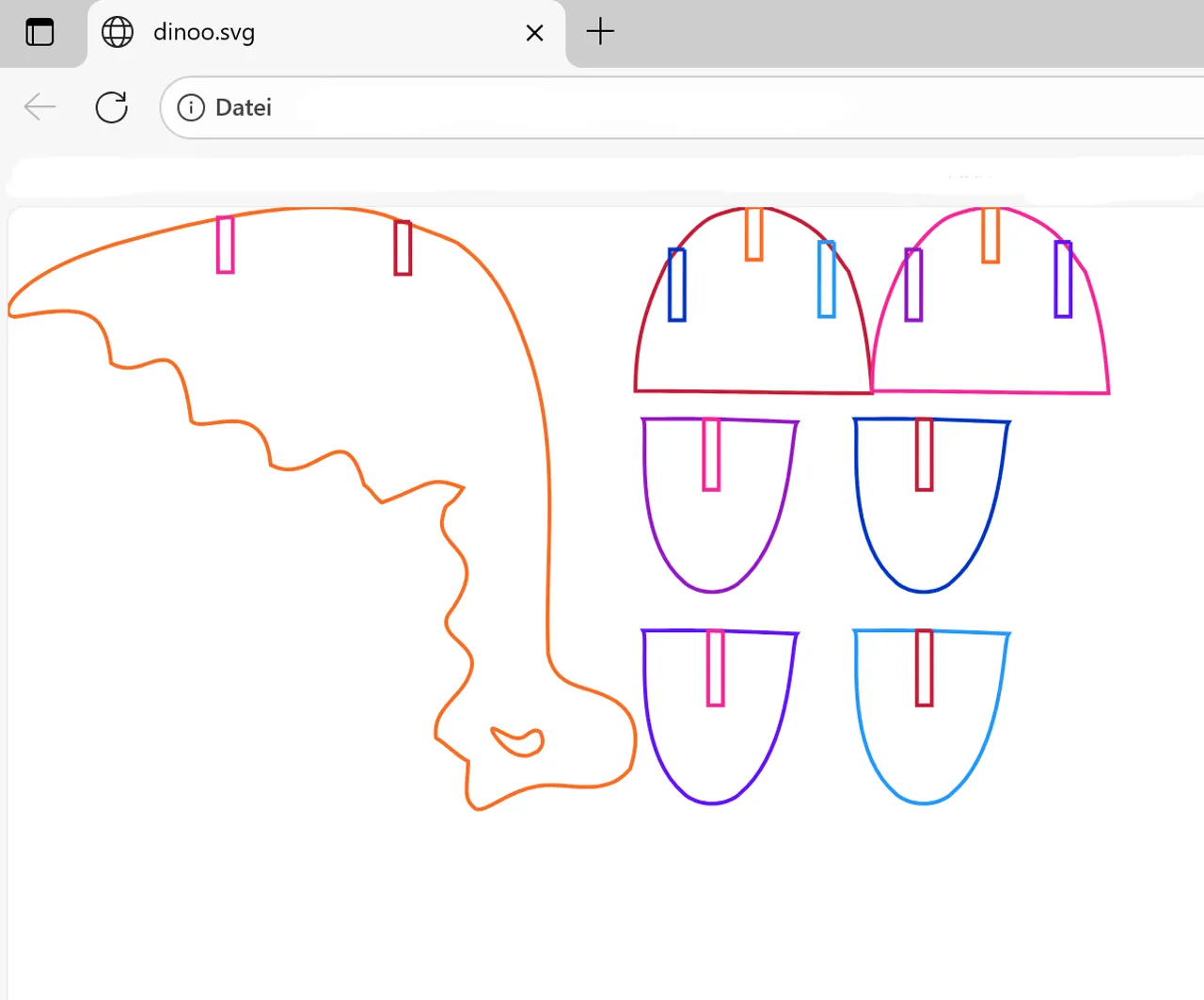
This is the SVG file you get:
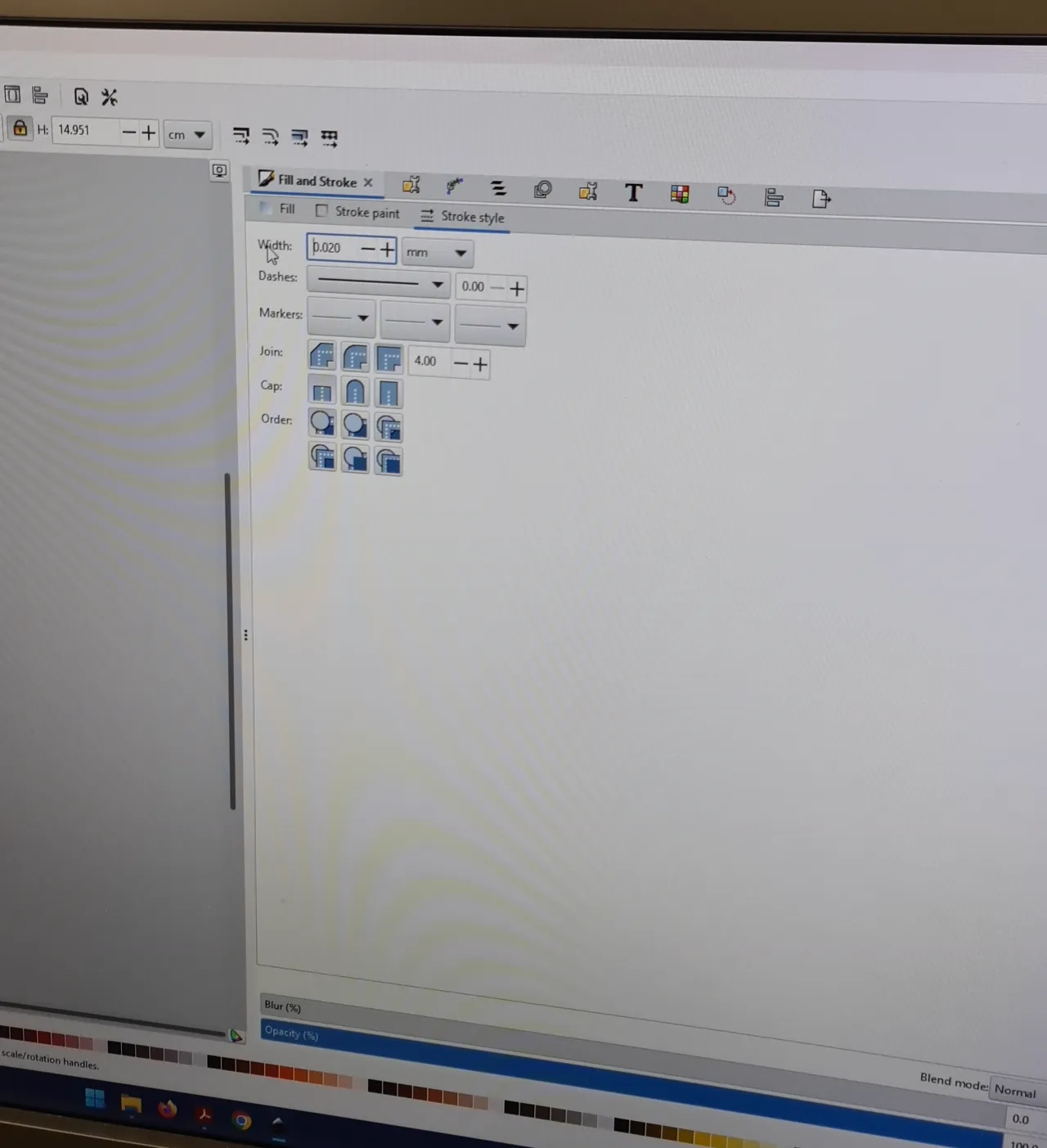
I opened it in Inkscape and did some changes: adjusting the colour to black, the line width to 0,02mm and pulled some slots (rectangles) closer to the edges.
Manufacturing FlatFab Model
Now that the model is done, the manufacturing process starts. I went on to calibrate the slot width to have a proper press fit. To control this, FlatFab had disappointing features, not allowing to input a kerf value but to set a Calibration-slider from 0% to 100%. The Calibration-slider is the Kerf in that case. It decreases the thickness of the slot (which is the material-thickness at 100%) - that way you can simply calculate the kerf with this percentage.
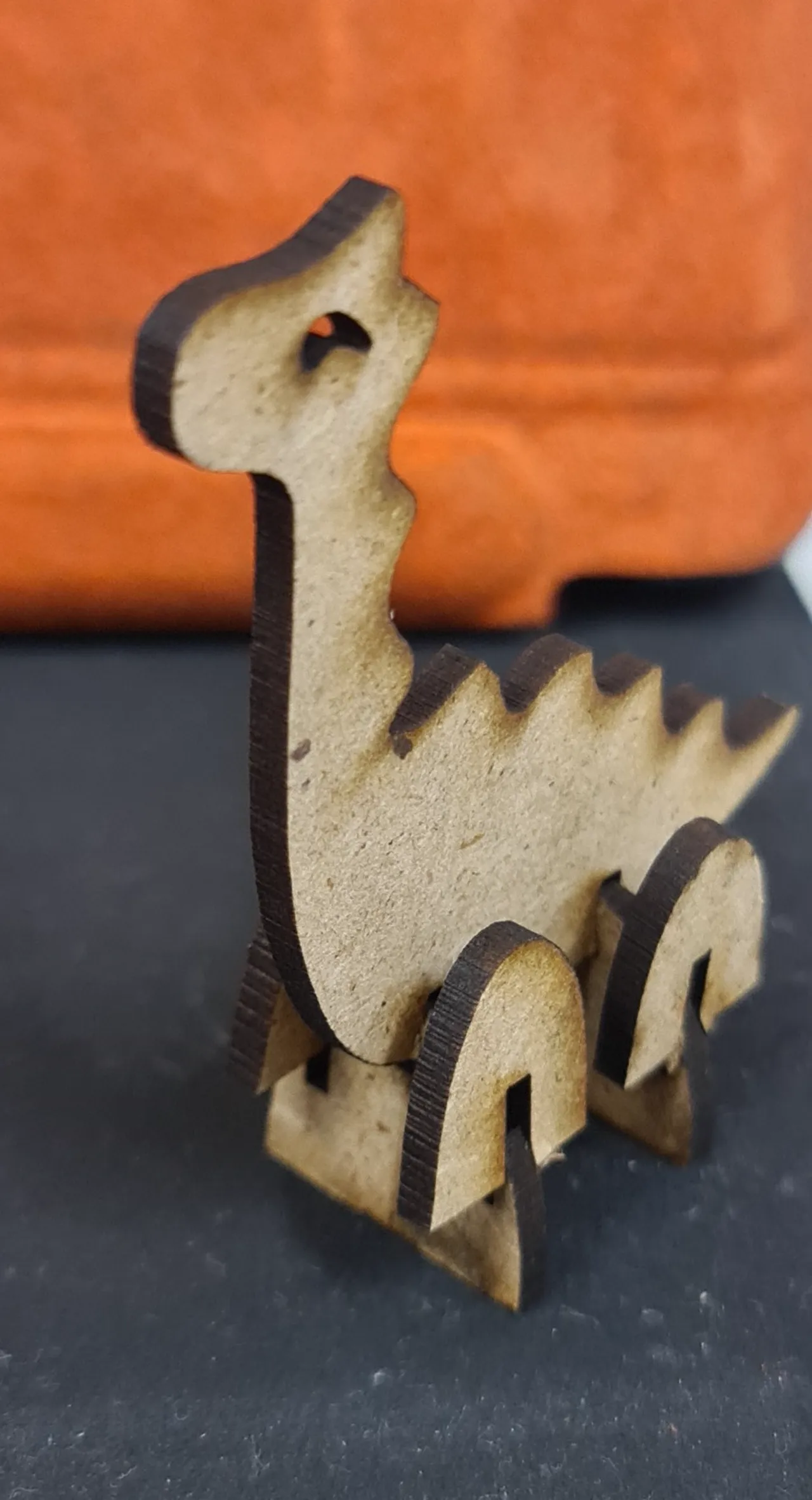
I tried to print the dino in a smaller scale with the Calibration of 95%.. but it turns out, that it was way too narrow:
After that I created a test figure to see the difference it makes if the value is changed.
Only 100% was kind of fitting and reducing this value only made the slot too narrow:
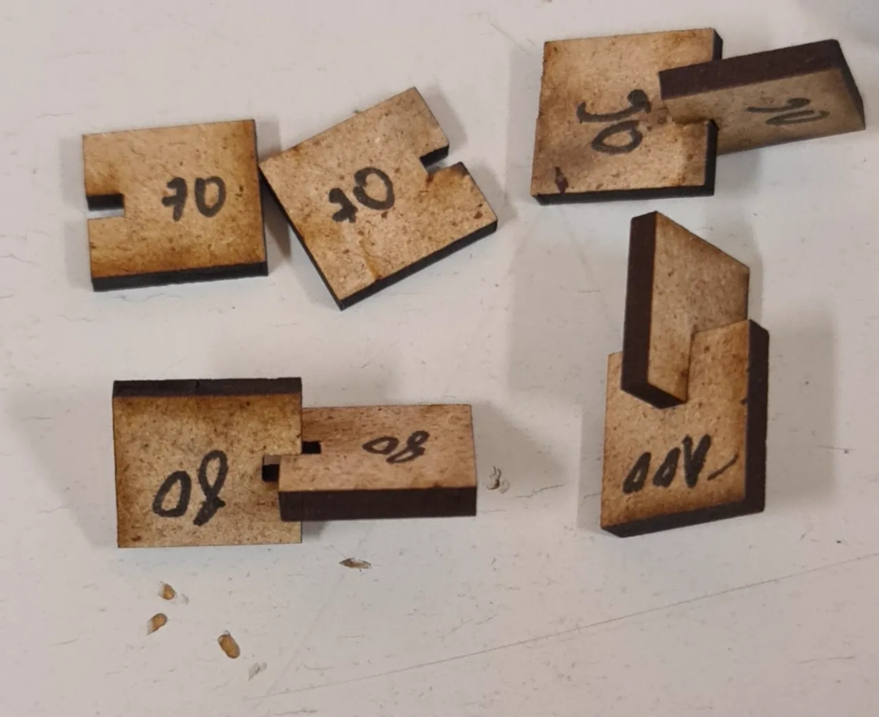
So unfortunatley the Calibration-slider does not really work for this Laser cutter. I had to find another way to identify the kerf:
The used material had a thickness of 2,6 mm. I went along testing slight differences in material thickness. Together with a friend, we generated multiple .svg files with varying material thickness. We copied them altogether in a single inkscape file and added text that should be engraved and show the material thickness. I tried values from 2,55mm to 2,7mm. 2,65mm showed the best press fit:
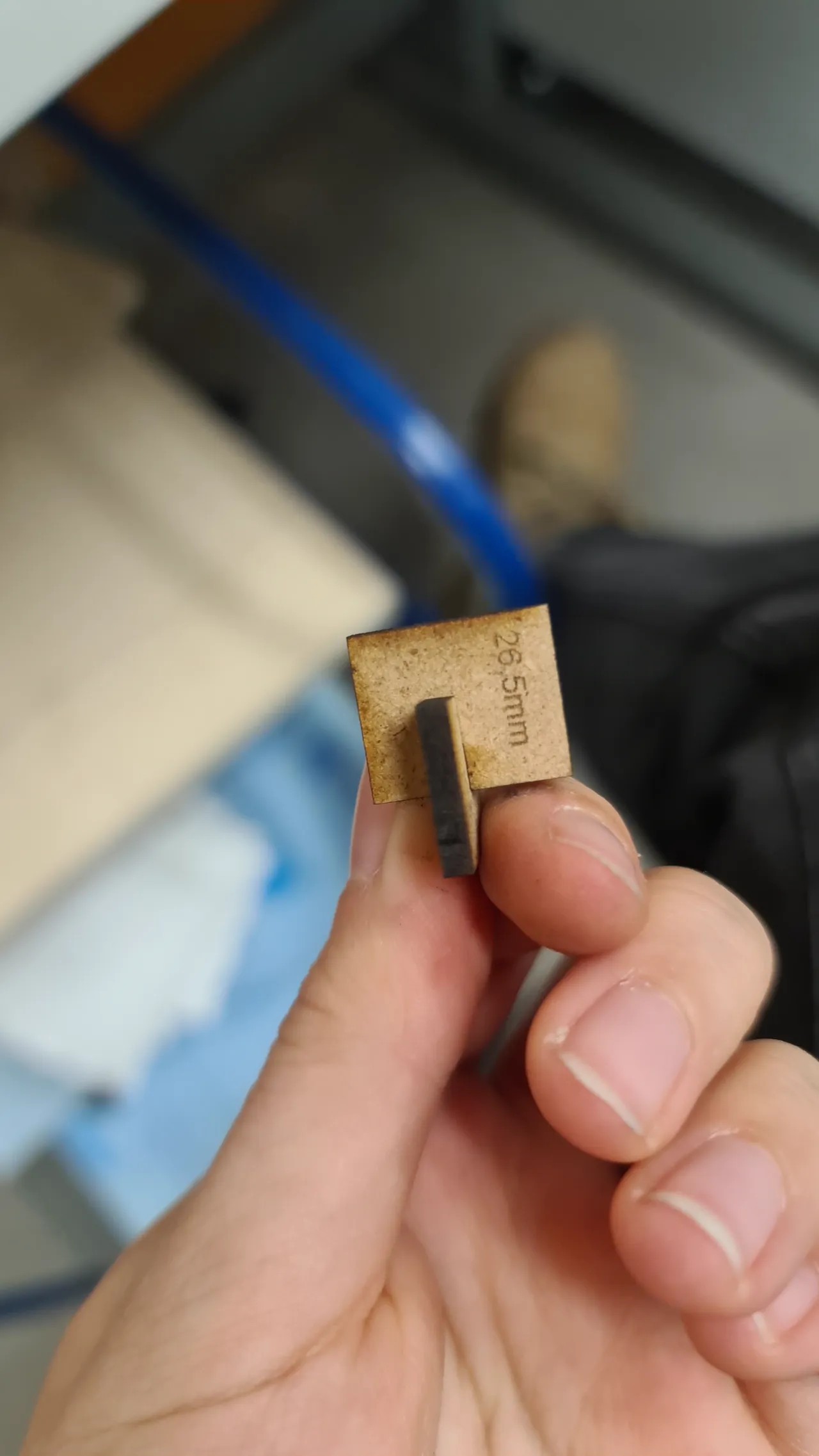
don’t be confused by the 26,5mm engraving: it was a mistake
To calculate the kerf, you can measure the slot width in Inkscape and compare it to the actual slot width of your model, then divide one by the other. Using this method, I arrived at a kerf of 0,5mm.
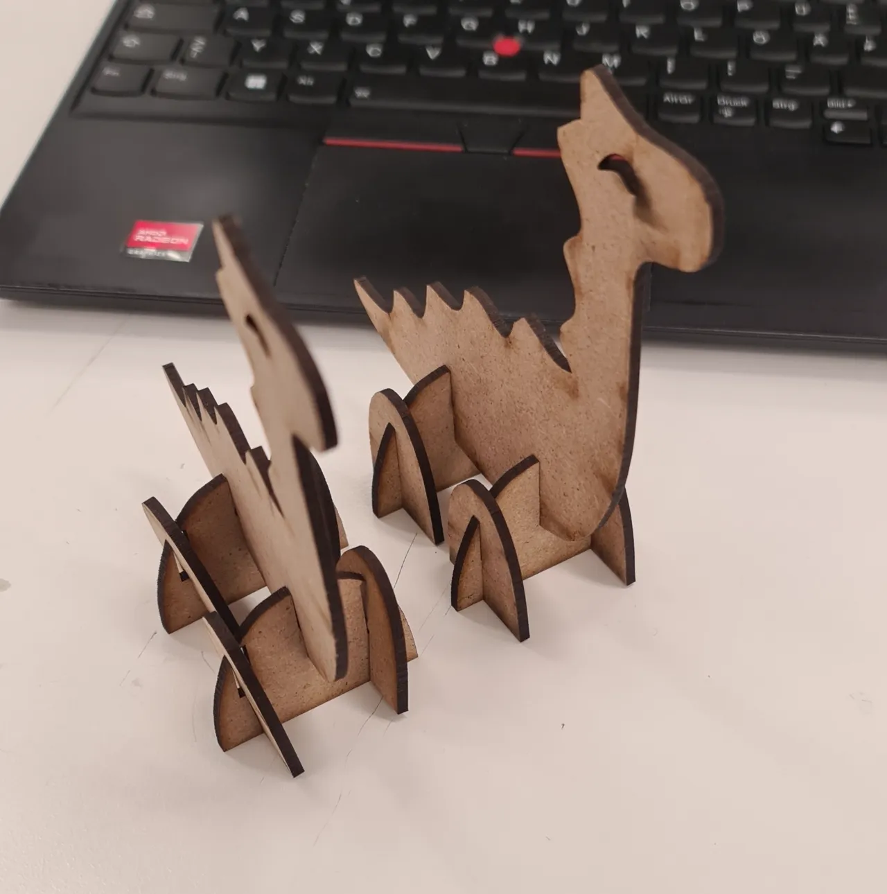
With that information I created the svg-file again with 2,65mm material thickness (although the material was 2,6mm) and lasered all the parts of the cute dino:
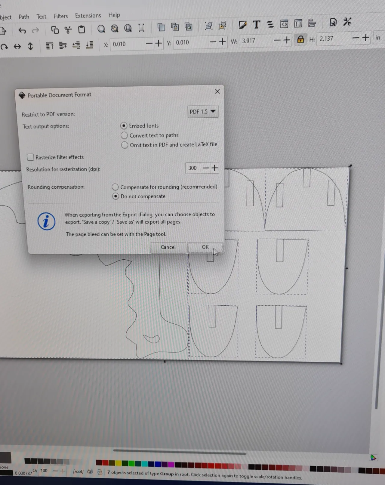
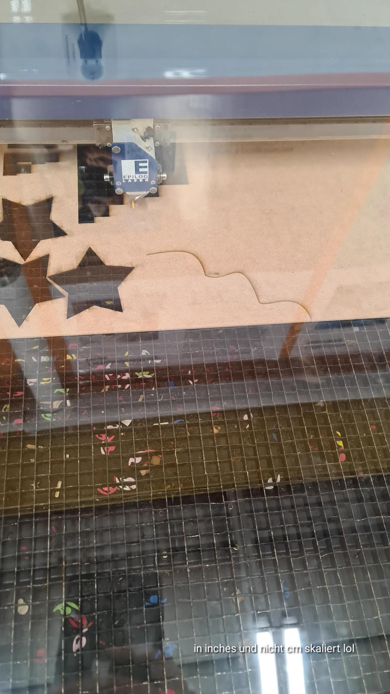
Careful! Check twice if you scaled it in cm or inches!!:
Here you can see the dinosaur without pulling the slots (left) and with adjusting the slots (right):
Vinyl Cutting
The vinyl cutter in Fab Lab Oulu is a Roland GS-24.
I followed these steps to use it:
- Prepare the vinyl roll:
Place and adjust the vinyl roll using the lever on the left side of the machine. The pinch rollers should be aligned with the white grit marks and you need to load the material aligned with the pinch rollers.
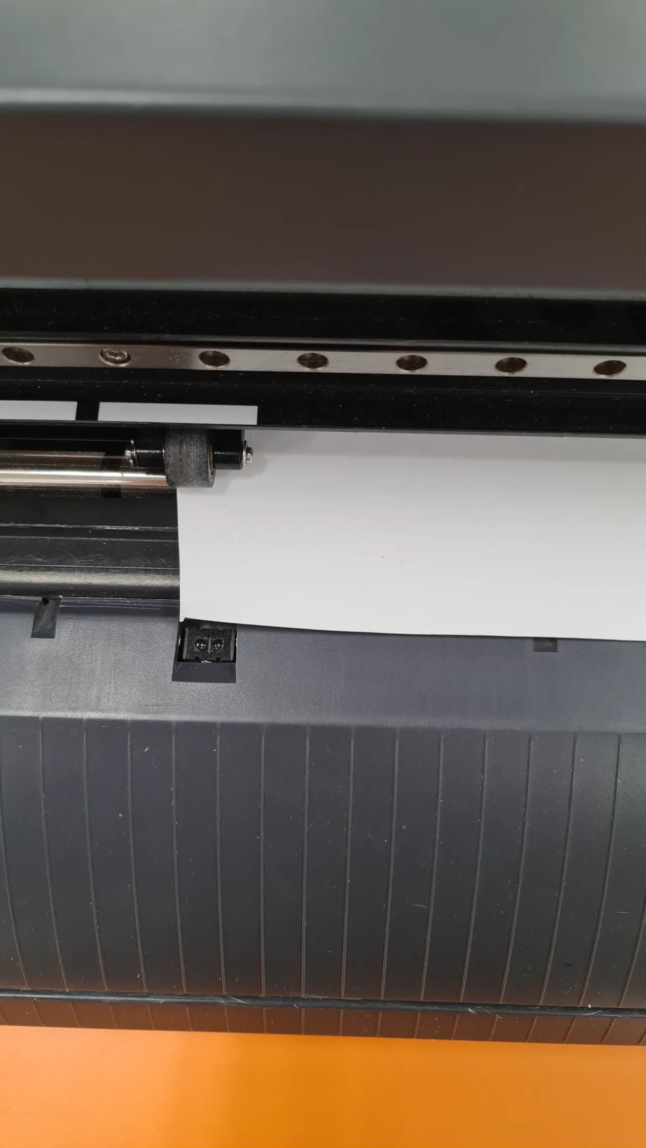
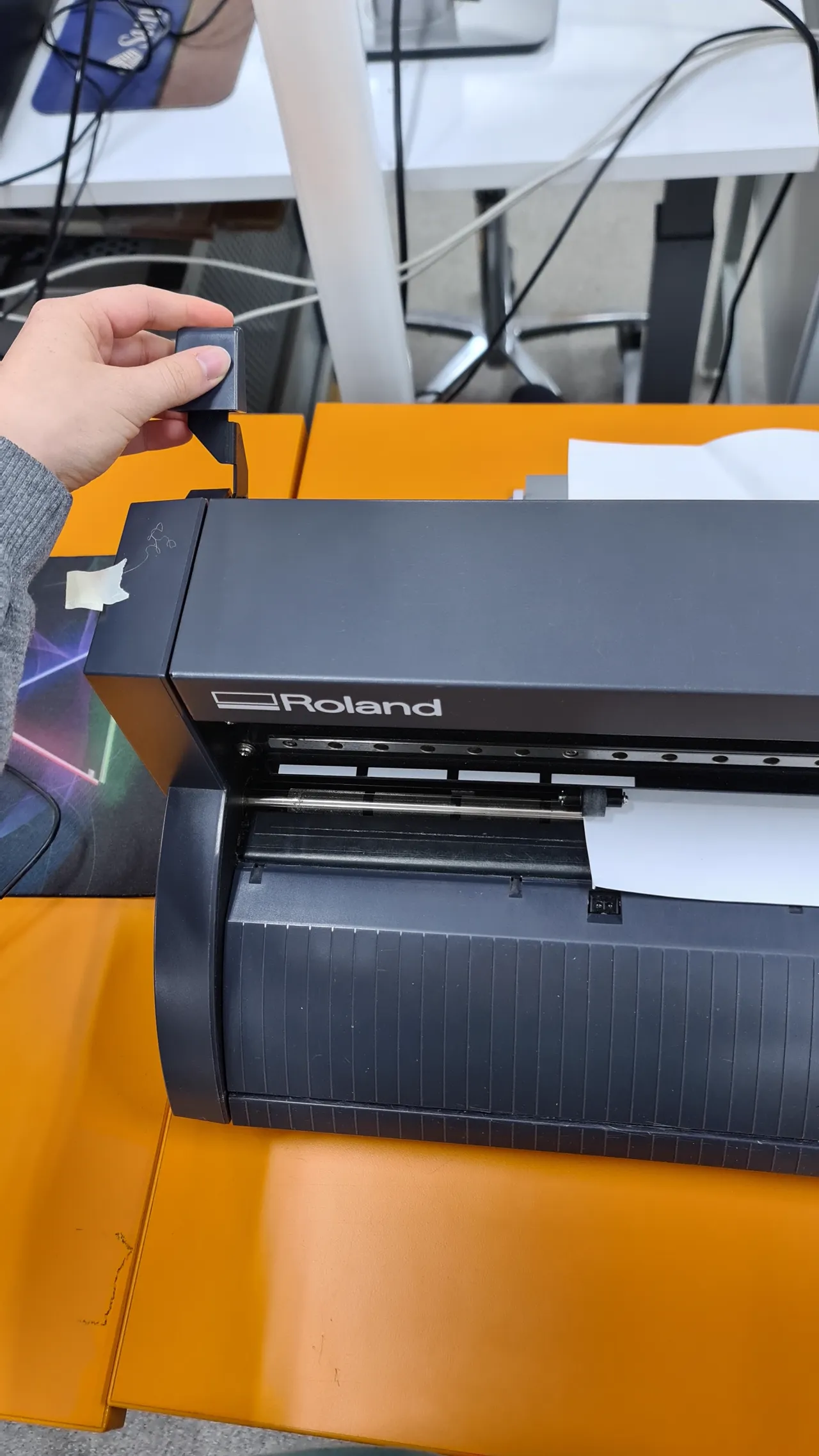
sensor in the back and front has to be covered by the material
-
Select the material type: On the machine choose between Piece, Roll or Edge depending on your material:
Piece — for small individual sheets (if your piece is too small just tape it on a piece of paper)
Roll — for continuous rolls
Edge — similar to roll, but the origin cannot be adjusted vertically
Confirm your selection by pressing ENTER
-
Set the origin: Move the blade to the desired starting point using the arrow buttons on the right side of the machine. When the blade is in position, press and hold the Origin button to save the starting point.
-
Prepare the file in Inkscape:
-
Import or create your SVG design.
-
Make sure the origin of coordinates is at the bottom-left corner of the canvas.
-
For my project, I made a Moomin sticker. I started with an image, used Trace Bitmap in Inkscape to convert it into a vector and then manually drew an outline around it for cutting. (detailed description in the bottom)
-
-
Cut the file:
-
in Inkscape go to Extensions -> Roland CutStudio -> Open in CutStudio
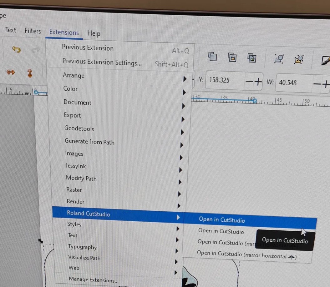
-
in CutStudio go to Cutting -> OK
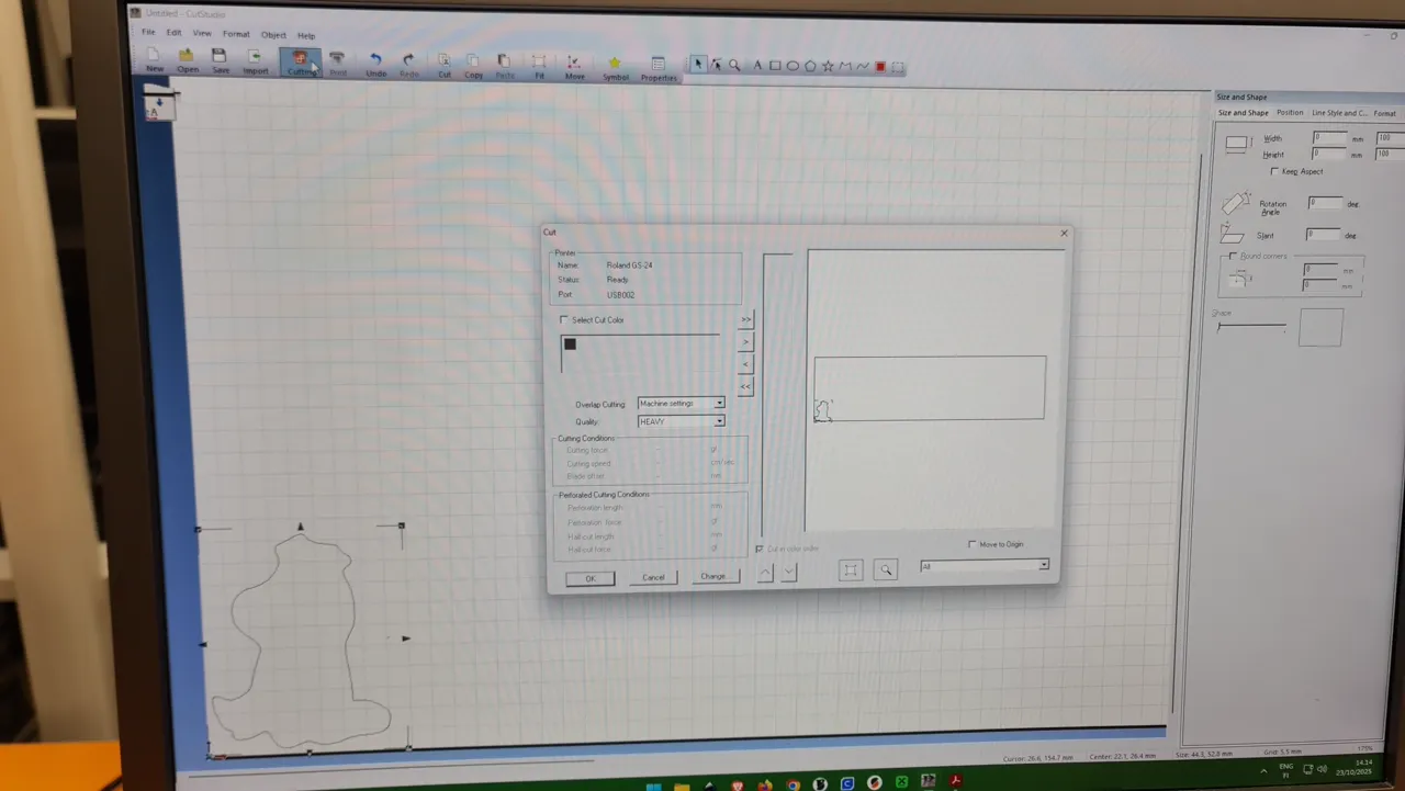
-
-
Final step: After cutting, I printed the colored image separately.

-
i.a. use tweezers to peel off the sticker:
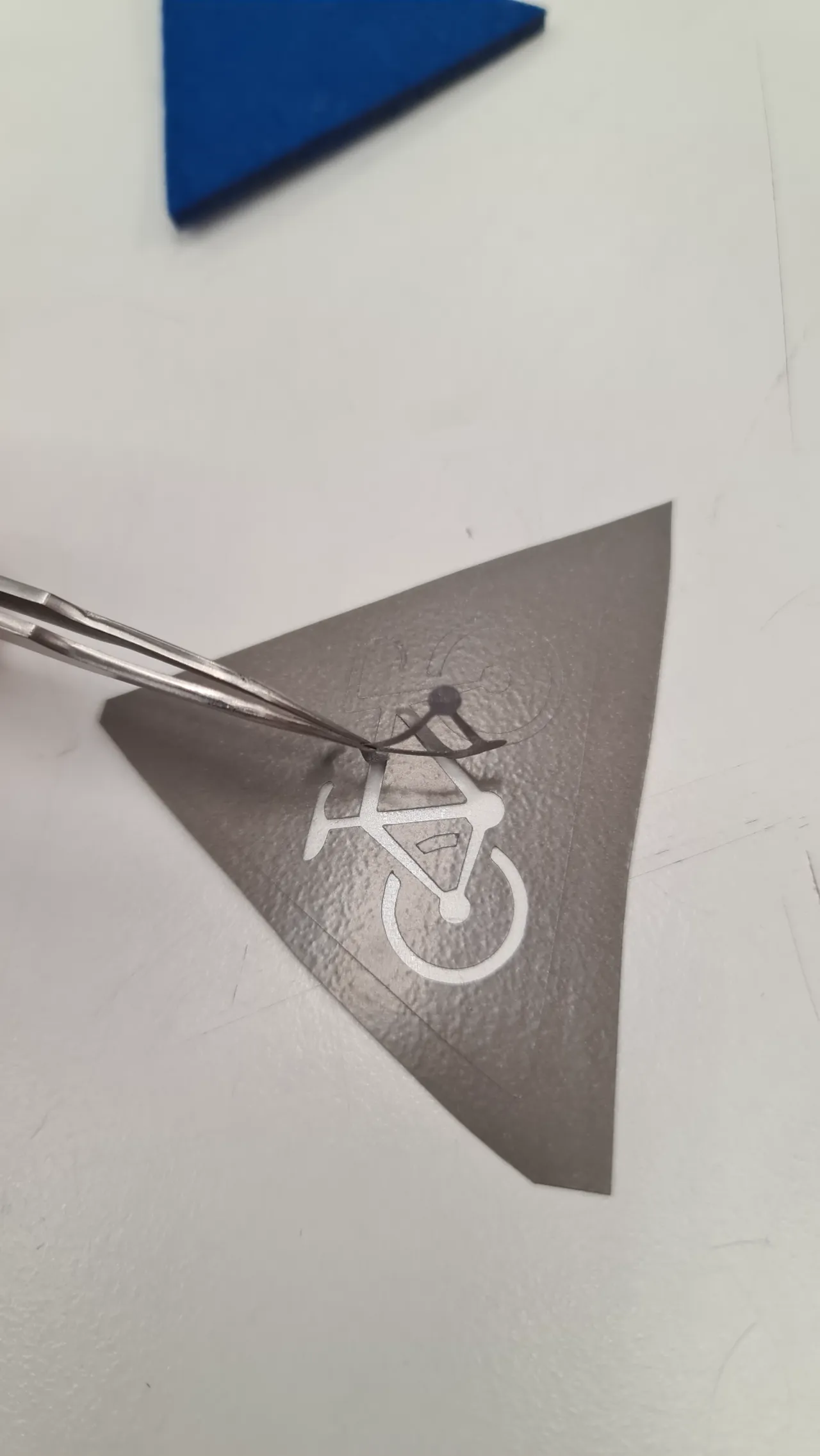
I simply peeled off the moomin sticker and put it on my phonecase: 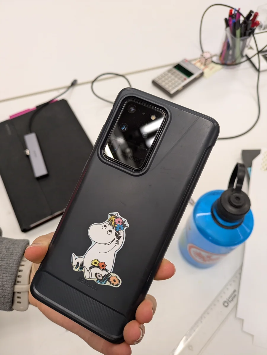
Moomin Sticker Inkscape
First I inserted the template which you can find here:
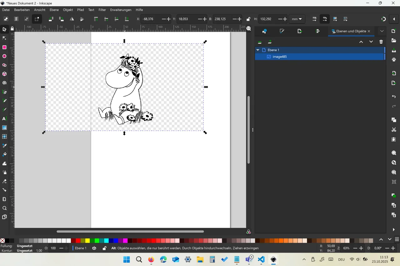
Next I traced the bitmap:
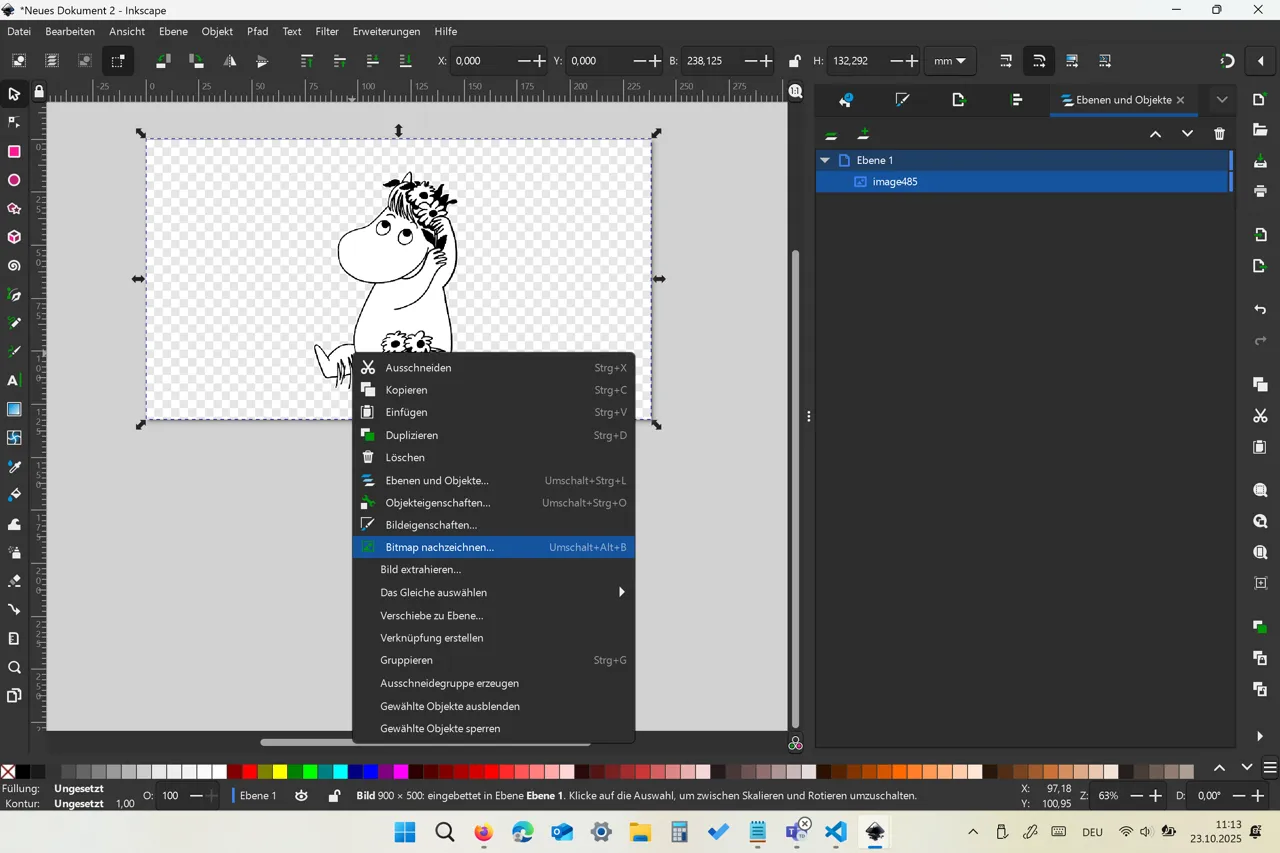
Here is the created bitmap:
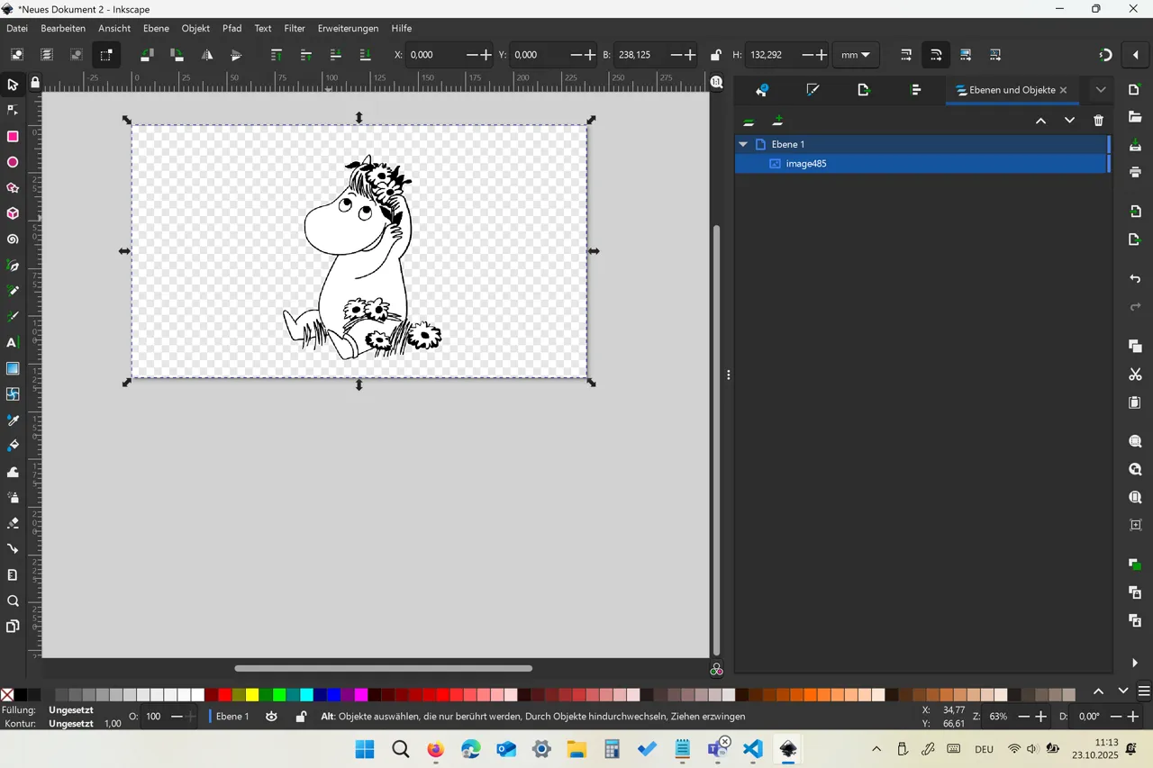
Now just delete the original picture:
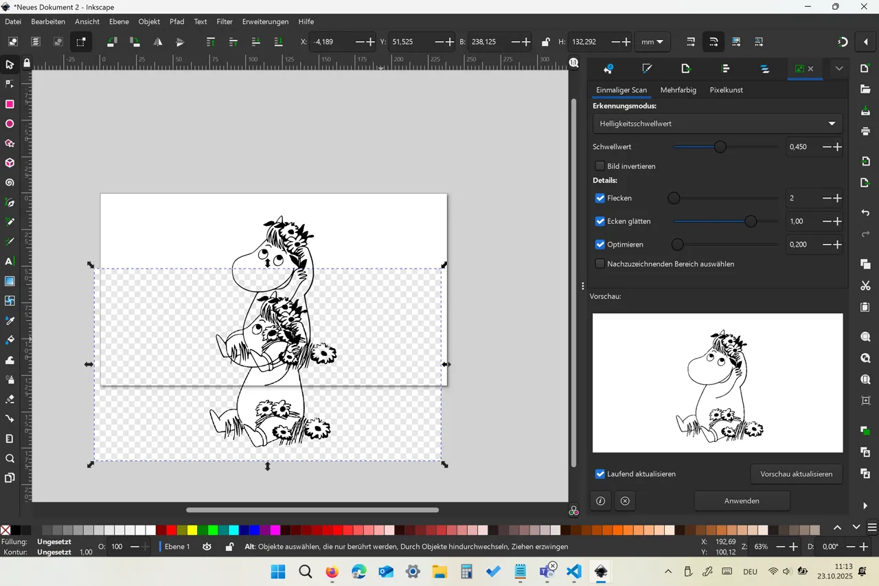
And you get left with the final graphic:
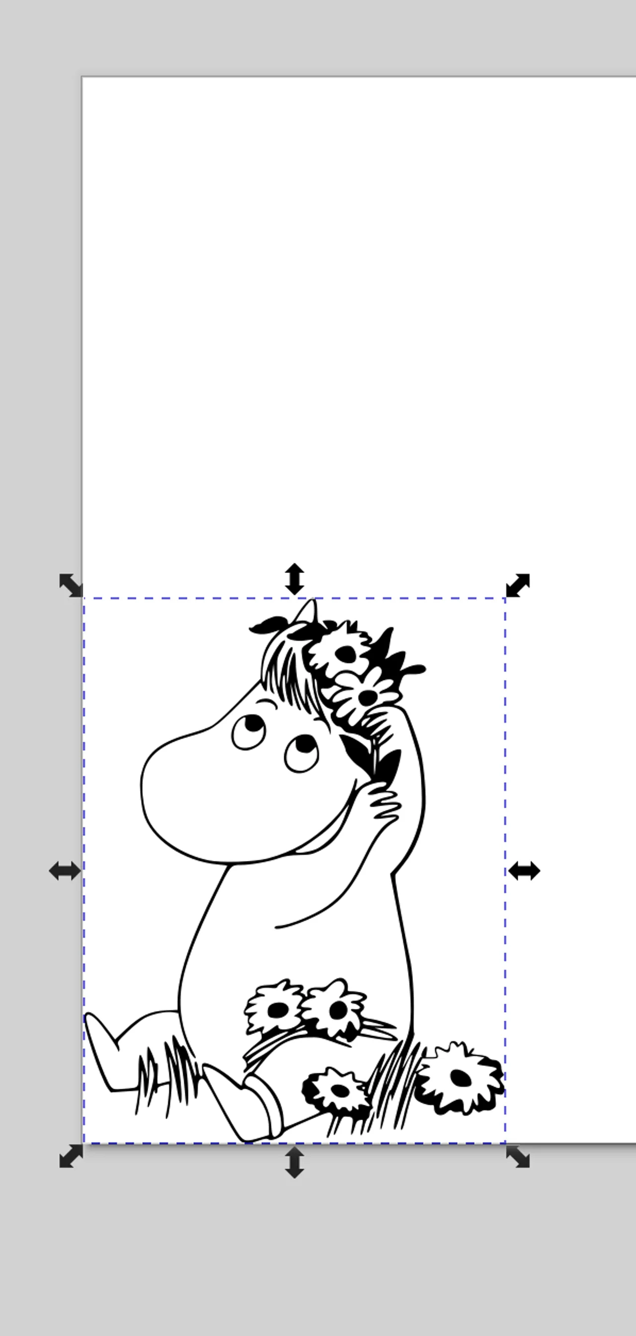
I adjusted the page size so I don’t have to worry about the placement when sending it to Roland CutStudio as it will automatically set the starting point in the lower left corner:
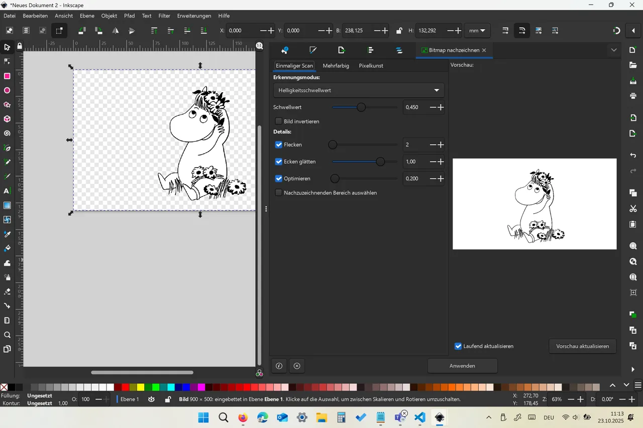 with ctrl + shift + R
I wanted to have a bit background, so I manually drew an outline by pressing B and then just setting points around the graphic:
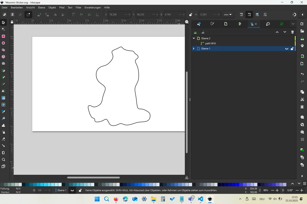
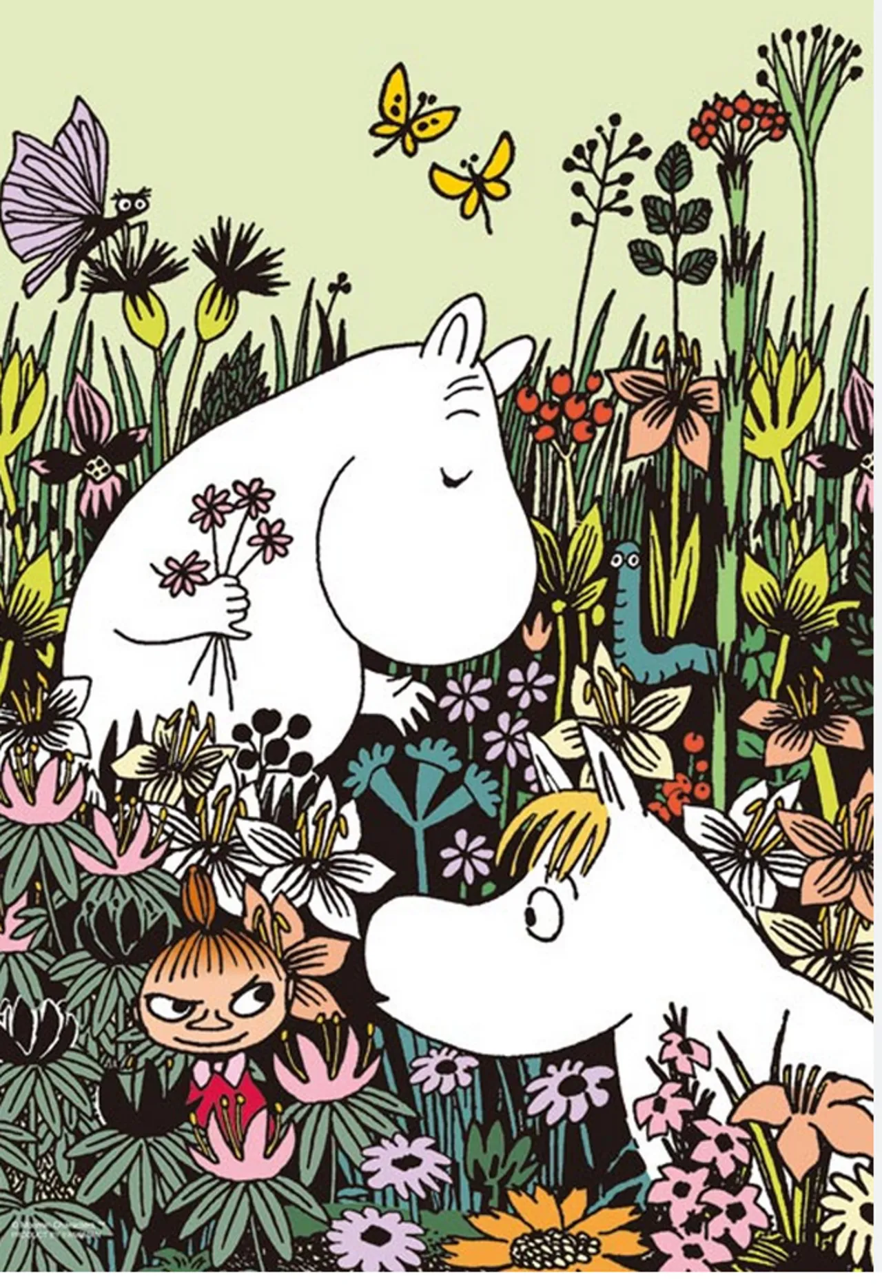
A black and white sticker is a bit boring, so I added some colours. I wanted the colours to be the same as in other moomin pictures, so I used another picture as reference again:
Here is the final sticker template: 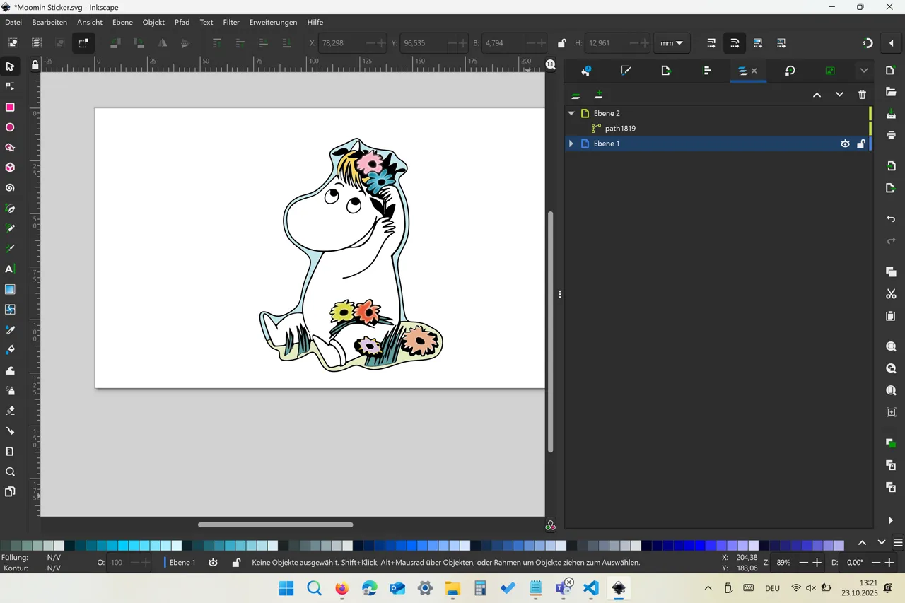
Link to models
- Inkscape Moomin Moomin Sticker.svg
- FlatFab model dino.txt
- Dino 3D-model dino.stl